Visa & Mastercard
Debit/Credit Payments Accepted
“To every action there is an equal and opposite reaction” is one of Newton’s famous laws. This is easily understood by thinking of a person swimming. The water is pushed backwards (that is the action) and your body is propelled forwards (equal and opposite reaction). Consider one further example: the wheels of a motor car revolve, the tyres push backwards on the road and the car moves forward.
So how can this simple idea explain whet happens to an aircraft in the air? To answer this question it should first be realised that air, too, is a substance like water and if you like - the road or ground. Consider what happens whenever there is a strong gale, for example, it may be difficult to walk or it may be possible to lean against the air currents. This proves that air is a real substance, even though it is invisible.
On fixed wing aircraft, it is the wings that produce the LIFT (which balances the weight of an aircraft, if the lift of an aircraft is greater than the weight, then the aircraft rises - and vice versa). To demonstrate how ‘lift’ is produced by a wing, a simple experiment is shown.
A Hold a piece of card so that it is slightly raised at the front (similar to a real wing).
Push the card forward fairly rapidly, and you will see the card rise and try to fold backwards.
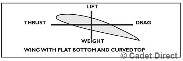
This is very similar to what happens when an aircraft speeds along the runway - the wings produce enough LIFT to carry the aircraft off the runway. It is now possible to look at all the forces that act on a real wing.

is the result of the power from the engine(s) DRAG is the resistance produced from the whole aircraft. So far we have seen that LIFT is the key factor.
But how is this LIFT produced?
To explain this, consider another experiment.
Blow along a sheet of paper, lift is produced. By blowing along the piece of paper, notice it rises. Now consider a typical aircraft wing:
A simpler way to imagine all these forces acting on the wing, is to sum these up and show them as a single arrow.
This is obviously an easier way to show the LIFT FORCE than drawing lots of arrows. It is also normal practice to show this single arrow acting at one particular point on the wing -known as the Centre of Pressure. See the diagram on the next page.
This is similar to balancing a ruler on your finger by finding the centre of gravity - i.e. the middle of the ruler.

The amount of lift a wing produces depends on a number of factors:
1. The airspeeds of an aircraft.
2. The angle of attack.
3. The air density.
4. The shape of the wing cross-section.
5. The total wing area.
Naturally, if the speed of an aircraft is increased (as it speeds along the runway) the more and more LIFT is produced. The angle of attack of an aircraft (that is the angle at which the wing meets the on-coming air) can also be varied to produce lift.
Clearly, if one was to measure the distance travelled along AIRFLOW ‘A’, and compare it with that travelled along ‘B’ then one would realise that distance for the first airflow is much greater than the second. But notice they start and finish together.

This must mean ‘A’ travels faster than ‘B’ in order to finish together because it has to travel a larger distance. The only way ‘A’ can travel faster is that the pressure above the wing(path ‘A’) is reduced and the pressure below the wing is still the same as it was at the start or the finish. This PRESSURE DIFFERENCE is known as LIFT, and since the pressure at the bottom of the wing is greater than the top, then a rise or lift is achieved.


Consider the cross-section of a typical wing as illustrated below, it can be seen how much LIFT is produced at every point on the wing. The lift forces are shown in the diagram by the length of the arrows. Greatest lift is, of course, produced in the middle of the area.
Thrust is in fact identical to what is commonly known, in the motor vehicle, as power. Just as a motor vehicle needs to produce continuous power to remain in motion, so too does an aircraft. DRAG Any object that moves through the air has to overcome the
or the resistance before it can move in the desired direction. A car experiences two types of resistance. Firstly, there is the friction between the road and the wheels, and secondly,
there is resistance from the air. However, in an aircraft only the air resistance need be considered. The more aerodynamic and smooth the surface of an aircraft or a car the less DRAG it produces. There are three main parts which make-up total DRAG of an aircraft:
there is resistance from the air. However, in an aircraft only the air resistance need be considered. The more aerodynamic and smooth the surface of an aircraft or a car the less DRAG it produces. There are three main parts which make-up total DRAG of an aircraft:
1. Form Drag - total DRAG caused by the parts of an aircraft.
2. Skin Friction - smooth surfaces produce less friction.
3. Induce Drag - double the air speed, four times the DRAG; similarly, treble the airspeed, nine times the DRAG, and so on. LIFT AND WEIGHT IN STRAIGHT AND LEVEL FLIGHT If the LIFT is greater than the WEIGHT, an aircraft will CLIMB; and if the WEIGHT is more than the LIFT an aircraft will DESCEND. However, in straight and level flight, both the LIFT and Weight are equal.
The Stall Normally, air flows smoothly and continuously over and under the wings in flight, with some amount of Angle of Attack. However, if this angle of attack is increased beyond 15o then the airflow round the wing suddenly becomes turbulent, which causes the LIFT to DECREASE rapidly. This sudden and rapid loss of LIFT is known as the STALL. The result is that the aircraft descends rather quickly causing height loss which in some circumstances could be dangerous.
The stalling angle of a particular aircraft wing does not vary. But, the speed at which a STALL can occur varies from aircraft to aircraft. The stall can occur at high or low speeds.
Factors which influence the stalling speed are:
1. WEIGHT - Higher the weight, higher the stalling speed.
2. POWER - Greater the power, lower the stalling speed.
3. FLAPS - Lowering flaps reduces stalling speed, especially when landing.
4. MANOEUVRES - ALL manoeuvres increase the stalling speed, in particular, steep turns.
Control Column back, nose up.
Control Column forward, nose down.
Control Column to the left, roll to the left.
Control Column to the right, roll top the right.
Left Rudder, yaw to the left.
Right Rudder, yaw to the right.
An aircraft in flight has the freedom to move in three planes or three different ways:
PITCHING plane (lateral axis). ROLLING plane (longitudinal axis) and YAWING plane (vertical axis). Each axis passes through the centre of gravity of the aircraft, and the aircraft can rotate freely in any of these three planes. This is illustrated in the diagram on the next page.
To achieve movement in any one of these planes described an aircraft has three important ‘SURFACES’ or ‘AREAS’ which are used to achieve a required manoeuvre.
The Control Column (commonly known as the ‘stick’) is linked to two of these surfaces - the ELEVATORS (which produce a PITCHING movement) and the AILERONS (which produce a ROLLING movement.)
The Third surface is the RUDDER (which produces a YAWING movement), and is connected to the RUDDER Pedals.
FLAPS The main purpose of FLAPS is to enable aircraft to make landing approach at as safe and slow a speed as possible. FLAPS are lowered, used, mainly during landing, but can also be used for take-off and are raised when not in use to ‘fit-in’ with the rest of the wing - giving the best of two worlds. It will be realised that at say 30O, with increased lift, the stalling speed is reduced and consequently a slower, safer approaching and landing speed is possible.
But at full FLAP, say 70O although there is a further reduction in the stalling speed, there is a most definite increase in the DRAG which results in a steeper approach angle and a better view for the Pilot as shown in the diagram, below.
ADVANTAGES OF FLAP
1. Steeper slower approach, better view.
2. Lower touch-down speed, reduced landing run.
3. Braking effective more since low speed.
4. About 15Oof Flap makes take-off more efficient.
In the previous pages we explained how varying the position of a surface (the ELEVATORS, AILERONS or the RUDDER), causes the aircraft to move about a particular axis.
These three surfaces also have additional ‘Mini-Surfaces’ called TRIMMING TABS, known as the ELEVATOR, RUDDER and AILERON TRIMMING TABS, respectively. These extra parts often play an important role.
If a Pilot tries to maintain a particular direction by flying ‘straight and level’ they have to ensure that a ‘BALANCED’ flight is achieved. This is only achieved if the Pilot is at all time conscious of what is happening to the aircraft, and if it ‘DRIFTS’ the Pilot has to correct it in order to maintain his FLIGHT PATH.
To relieve the Pilot of constantly having to adjust the aircraft, the Pilot can ‘TRIM-OUT’ using the TRIMMING TABS to achieve a well balanced aircraft -and now of course the Pilot is free to concentrate on other important activities - such as navigation.
HIGH SPEED FLIGHT - SPEED OF SOUND
You may have noticed that when a batsman strikes a cricket ball there is a delay of a fraction of a second between seeing the ball hit and actually hearing the noise of the strike. Similarly, lightening flashes can be observed several miles away yet the thunder is heard a few seconds later.
When noise is generated, at the source, air is rapidly compressed and pressure waves are formed which travel through the air until they reach the ear - these are known as sound waves. These sound waves all travel at the ‘speed of sound’. Sound Waves travel at different speeds in different air temperature. This can be realised by the fact that temperature of air falls off with height and so does the Speed of Sound.
Consider the figures in the table below;
The Mach Number is the ratio of the true airspeed of an aircraft to the ‘LOCAL’ speed of sound. If the local speed of sound is 600 mph and the aircraft speed is 1200 then the MACH number is 2 - displayed on a Machmeter.
When an aircraft is travelling below the speed of sound, air ahead is ‘warned’ of a approaching aircraft and makes way by separating so that the aircraft flies through smoothly. If however, the aircraft is travelling at the speed of sound then the air of course has no time to make-way and the effect is that the air strikes the aircraft and noise and vibration can be heard - this is known as the SHOCK WAVE. Furthermore, the higher the speed of the aircraft above the speed of sound the further back the shock is relative to the aircraft.
Some terms commonly used are listed below:
SUBSONIC - under the speed of sound.
SONIC - at the speed of sound.
SUPERSONIC - above the speed of sound.
On all aircraft four forces act:
LIFT WEIGHT THRUST DRAG
If any of these forces are disturbed (from a straight and level position) then the aircraft will either climb or descend, accelerate or decelerate. The forces acting on a Glider are the same as those on an aircraft with the engine power reduced to zero.
This means the aircraft or glider will descend, that is GLIDE towards the earth due to it’s own weight.
Naturally, the Pilot wants the glider to travel as much distance as is possible. To achieve this, the DRAG factor must be kept to a minimum because this ensures that the ratio LIFT/DRAG is maximum and hence, the further the glider will travel.
This minimum DRAG is attained at a angle of, usually 1 in 19 - that is, at a height of one mile, a glider will travel 19 miles before touch down.
There are several ways of ‘launching’ a glider;
Aero-Tow - A powered aircraft tows the glider behind it using the tow rope and is released at whatever speed the Pilot choses.
Auto-Tow - A tow rope is attached to a car which is driven at high speed in order to launch the glider.
Bungee - This uses the Catapult principle. The glider is normally launched at the edge of a slope by a ‘V’ shaped strong elastic rope - and when released the tension on the rope is enough to raise the glider to a small height.
Winch Launch - This is the most common method used. A powerful winch and engine draws a 1000 yard steel cable to which a glider is attached and quickly launched. Typically 1000 feet is achieved with a 1000 yard cable.
A glider has similar type of control surfaces as any conventional aircraft, and similar controls to operate them.
The instruments usually include: Airspeed Indicator (AI), and of course a Variometer (an instrument which indicates whether an aircraft is rising or descending)
In the cockpit there is also a control which operates the spoilers - these are effectively air brakes.
The THERMALS, or rising hot air, is used by glider pilots to remain airborne as long as possible. In fact in a relatively large area there are many thermals, on a sunny day, which a Pilot ‘CONSUMES’ until a certain height and then moves onto another thermal thus continuously gaining height and in the process remaining airborne for a longer period.
is a mass (or a quantity) of air which moves upwards when it is warmed for, by example the sun, green fields or lakes (they take much longer to heat than tarmac or built-up areas and these result in thermals being formed as shown in the diagram below.